TCG-4
15 Maggio 2019
powerMELA.bc
17 Maggio 2019M01
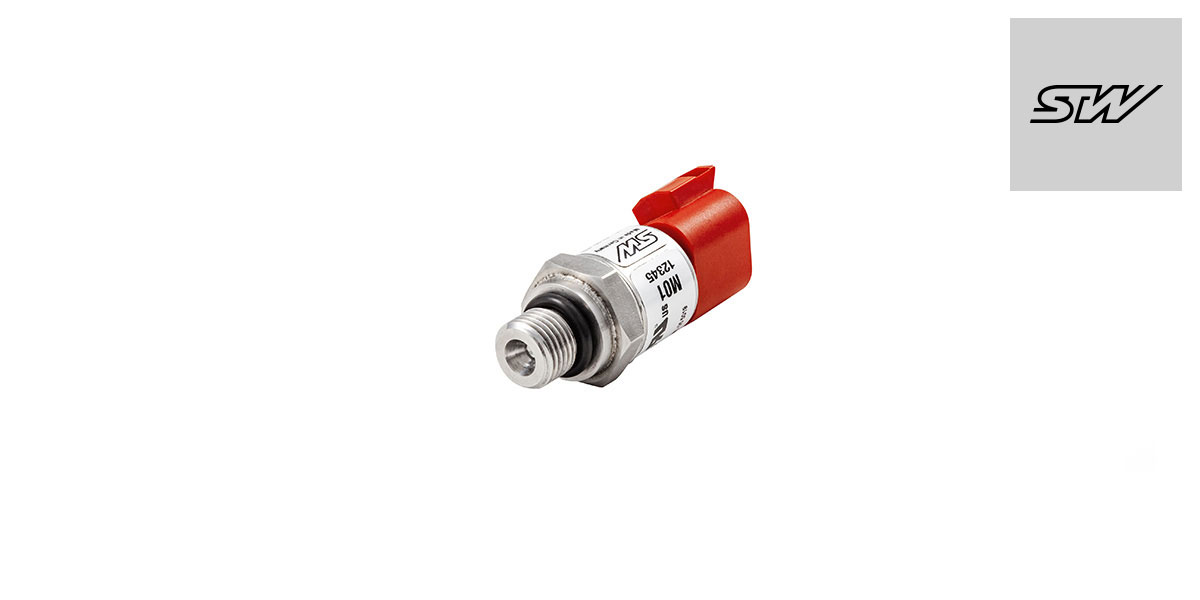
Pressure sensor
The Pressure Transmitter M01 has been developed especially for use in commercial vehicles and mobile machines. It is based on a thin-film measurement cell made from stainless steel which is welded together with the pressure sensor and thus guarantees high media compatibility.
TECHNOLOGIES
The mechanical and electronic characteristics of the M01 series have been especially designed for applications in adverse ambient conditions; in the same way value is placed on high resistance to aggressive media. Furthermore, the modular principle of the M01 series permits a large number of combinations of pressure connection, pressure range, electrical output signal and electrical connection, meaning that the right pressure transmitter can be found for almost any application. Over and above this, we also offer the possibility of producing and supplying OEM versions.
Silicon measurement cells are used for low pressure ranges from 0.25 bar to 4.0 bar. These can be used at media temperatures from −40 °C to +85 °C. For pressure ranges from 10 bar to 2000 bar, which are frequently required for use on mobile machines, welded stainless steel measurement cells are used which are suitable for media temperatures from −40 °C to +150 °C.
Depending on the type of measurement cell and the material coming into contact with the media, the M01 Pressure Transmitters are resistant to aggressive or non-aggressive gases and liquids. On request, versions in 316L design for use in hydrogen pressure measurements are available. In addition to CE and UL certificates, every product in the M01 series with a 1.4542 stainless steel measurement cell possesses an E1 approval verifying its suitability for use in vehicles.
Statements
M01 is a product of
Sensor-Technik Wiedemann GmbH
All rights are reserved.
Specifications
| Pressure range, gauge | 0 … 0.25 bar to 0 … 2000 bar, other ranges available | ||||||||||||||
|---|---|---|---|---|---|---|---|---|---|---|---|---|---|---|---|
| Pressure reference | relative R (gauge G) / absolute A | relative R (gauge G) | |||||||||||||
| Standard pressure range | 0.25 bar | 0.4 bar | 1 bar | 1.6 bar | 4 bar | 10 bar | 0 bar | 25 bar | 50 bar | 100 bar | 250 bar | 400 bar | 800 bar | 1200 bar | 2000 bar* |
| Overload pressure (per DIN EN 60770-1) | 0.63 bar | 1 bar | 2.5 bar | 2.5 bar | 10 bar | 20 bar | 40 bar | 40 bar | 100 bar | 200 bar | 500 bar | 800 bar | 1000 bar | 1600 bar | 2200 bar |
| Bursting pressure (per DIN EN 60770-1) | 0.75 bar | 1.2 bar | 3 bar | 3 bar | 12 bar | 30 bar | 70 bar | 70 bar | 500 bar | 1000 bar | 2500 bar | 4000 bar | > 4000 bar | > 4000 bar | > 4000 bar |
| Media temperature | −40 … +85 °C / -40 ... +185 °F | −40 … +150 °C / -40 ... +302 °F | |||||||||||||
| Operating and storage temperature | −40 … +85 °C / -40 ... +185 °F | −40 … +125 °C (-25 … +85 °C at cable output) −40 … +257 °F (-13 … +185 °F at cable output) |
|||||||||||||
| Material with medium contact | Stainless Steel AISI 630 (DIN 1.4542) and Silicon (For applications with non-aggressive gases and fluids or substances which do not react with glass or silicon) | Stainless Steel AISI 630 (DIN 1.4542), AISI 316 L (DIN 1.4435) on request |
|||||||||||||
| Overall accuracy at operating temperature | ≤ 1.0 %FS (0 ... +85 °C) / (32 ... +185 °F) ≤ 2.5 %FS (−40 ... 0 °C) / (−40 ... +32 °F) | ≤ 0.5 %FS (0 … +105 °C) / (32 … +221 °F) ≤ 1.5 %FS (−40 … 0 °C and +105 … +125 °C) / (−40 … +32 °F and +221 … +257 °F) |
|||||||||||||
| Thereof linearity, pressure hysteresis and repeatability (Linearization with limit point setting) | < 0.25 %FS | ||||||||||||||
| Material wetted parts and housing | Stainless steel, AISI 304 (DIN 1.4301) | ||||||||||||||
| Material connector | glass-fiber reinforced plastic (PBT) or AISI 304 (DIN 1.4301) | ||||||||||||||
| Installation torque | max. 35 Nm | ||||||||||||||
| Long-run stability | < 0.2 %FS p.a. | ||||||||||||||
| Voltage supply (DC) | U VCC : 9 … 36 V U VCC : 14 … 36 V (for transmitter with 0 … 10 V voltage output) U VCC : 5 V ± 10 % (for transmitter with ratiometric output) allowable ripple at 50 Hz: 10 % |
||||||||||||||
| CAN | Sampling Rate Digital Filter Output protocol Electrical connection | 1000 Samples/s (max.) averaging adjustable STW-CAN, CANopen, SAE J1939 M12 connector, DIN Bayonet (per DIN 72585), DT04 4-pole, cable output |
|||||||||||||
| Analog | Output signal | 4 … 20 mA (2-wire technique), 0/4 … 20 mA (3-wire technique), 0 … 10 V, 0 … 5 V, 1 … 6 V, 10 … 90 %VCC (ratiometric output) Other output signals on request |
|||||||||||||
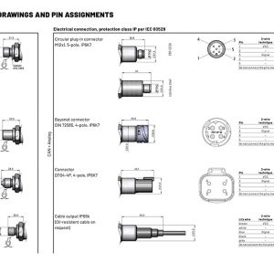
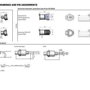
| Electrical connection | M12 connector, DIN bayonet (per DIN 72585); DT04 4-pole; DT04 3-pole, AMP-SuperSeal 1.5; cable output Other connectors on request |
||||||||||||||
| Electrical protection | Short circuit protected, signal on GND/VCC and inverse polarity protection (not at ratiometric output) | ||||||||||||||
| Pressure connection | G 1/4, 1/4 NPT, G 1/4 with manometer pin, SAE04 (7/16-20UNF), SAE06 (9/16-18UNF), other pressure connectors on request, possible limitations of the pressure range | ||||||||||||||
| Protection class | IP6K7 or IP6K9K (depends on the electrical connection) | #colspan##colspan# | |||||||||||||
| * For common-rail applications | |||||||||||||||
| Functional safety | |||||||||||||||
| Pressure switch M01 (analog and CAN) | Acc. DIN EN ISO 13849-1: Performance Level b Cat. = B MTTFd = High DC = None CCF = Not relevant |
||||||||||||||
- Optional software package for CAN interface setting parameters
Code: 1140203000200 PRESSURE SENSOR M01 G¼ M12


